VGA lag tester
Updated 4.6.2013
1. Introduction
Display latency has been a constant issue in the era of flat panel displays. Manufacturers have traditionally prioritized picture quality and post-processing in displays without much thought for how they would behave with games. It is not uncommon to find a flat display which buffers several frames before output. For many gamers, this added latency is unacceptable. Some TVs may provide "Game modes" which may or may not cut some of the processing, while often applying an unnatural color preset or limiting aspect ratio choice at the same time. However, still at 2013, the issue of display latency is not generally well acknowledged. Part of the reason may be that most games today are not that reflect-sensitive as in the good old days, but that's another topic and not discussed here...
Several display reviews have recently included latency measurements, which is a positive sign. These numbers are often measured by using an additional display with a known latency (ofter CRT), and taking a photo of a running counter mirrored on both displays. While this method works in principle, it's not very accurate (e.g. with some graphics cards, the mirrored displays may not be exactly in sync) and not very convenient. This led me to think a few years back if it would be possible to create a simple homemade system for measuring display latency. After some thought, I was confident that it'd easily doable by tapping analog RGB video signal with a microcontroller. For digital signal like HDMI, I'd need to use FPGA with HDMI transceiver chips, which would no more be a everyman DIY solution. However, one could use a converter with known latency (e.g. XRGB series) to measure digital inputs with the planned tester. Nowadays, a ready-made lag tester from Leo Bodnar is available, which is a good tool for testing display latency using HDMI.
I managed to build the device successfully and test my monitor back then. Sadly, this ended up as just another personal project and I hadn't time to write a proper article about it. Now that I've seen more interest among people to measure latency accurately, I decided to dig this up and collect here all required info and tools for building the device and measuring latency with it. The original PIC-based version had some limitations and is not very polished overall, so I did a new and improved version for AVR.
2. Display latency
The tester presented below measures display latency, which is here defined as the time difference between the video signal going into display and the corresponding pattern on the screen. I try to avoid using term "input lag", since that's context sensitive. If that term is used in this page, it will refer to the total latency between controller input and the corresponding action on the screen, in which display latency is only one factor among others. Display latency consists of processing latency (in display) and pixel response time, which are shortly described below.
Processing latency
Processing latency in display is the time between a dot/pixel in the input signal and the moment when a corresponding dot/pixel in display starts to change its state as specified in the signal. This varies a lot between displays, since some displays may buffer only a few scanlines, while others buffer several frames for post-processing. The refresh logic inside the display has also an effect on the processing latency. It takes a nonzero time to transmit the whole frame from top-left to bottom-right pixel to the display (e.g. ~16ms @ 60Hz), and the refresh can be handled in different ways depending if the panel internal refresh rate differs from the input signal rate. A CRT or a simple LCD refreshes at the same rate as the input signal, resulting in a similar difference in output between top-left and bottom-right dot/pixel. A 600Hz plasma on the other hand, needs to buffer at least one frame (assuming it won't refresh incomplete frames, which could result to visible tearing even at 600Hz), after which it refreshes itself almost instantaneously. In the latter case, display latency is not constant: top portion of the image lags almost one frame more than the bottom part. Therefore, the average display latency in these kind of displays is half-frame less than the worst-case.
Pixel response time
Pixel response time is the time it takes to turn a pixel from a state to another, e.g. from black to white. This value can be found in display specifications, and while it has a some contribution to total latency, it's more meaningful metric for throughput. A panel with high response time cannot be used with high refresh rate, or ghosting occurs. Typical response times are around 1-12ms for LCD, 300us-2ms for CRT, and 10-100us for plasma.
I've created 2 example timing diagrams based on my measurement results, which illustrate display latency. They also include imaginary game console input to show the relation between input and display latencies:
Eizo FS2333
Panasonic VT30
3. Lag tester
The lag tester (shown below) consists of a AVR microcontroller (ATMEGA88PA), character LCD display, photoresistor, button and LED. The basic working principle is simple: tap one component of the video signal, and calculate the time between input signal transition and corresponding display pattern. This setup requires a PC generating a suitable VGA signal - hence the name "VGA lag tester". It is also possible to connect the VGA signal to a SCART RGB input of a TV, if your graphics card can output suitable modelines and you build a small conversion circuit. It'd be probably possible to implement the signal generation with a bit more capable microconroller and tight assembly coding, but generating the signal outside allows more flexibility with resolutions, refresh rates etc. You also need a open a VGA (or SCART) cable, and solder wires to one color component (e.g. R) and the corresponding ground.You should get the required parts for under $30 (not including AVR programmer) from your local electronics store.
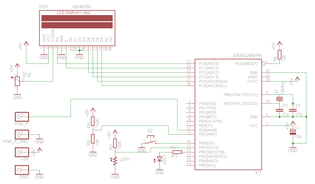
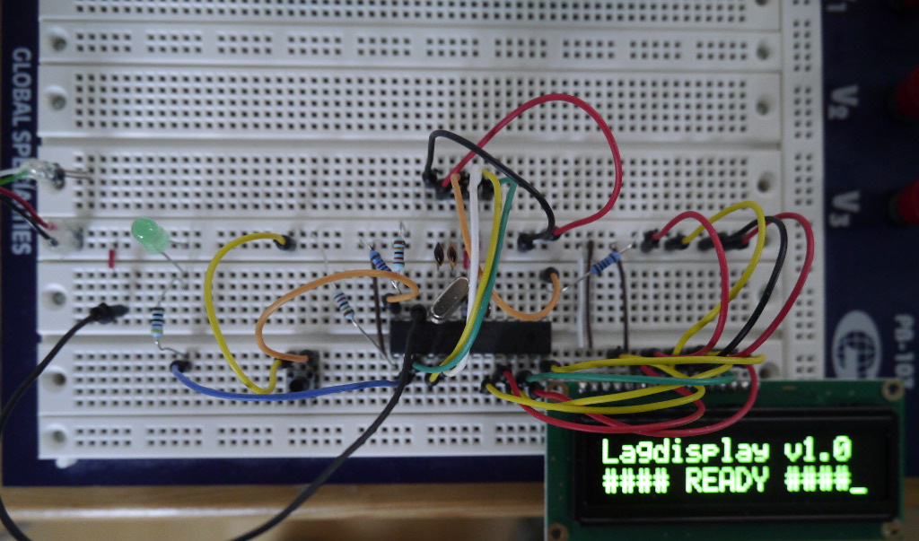
Schematic of the lag tester. The system on a breadboard.
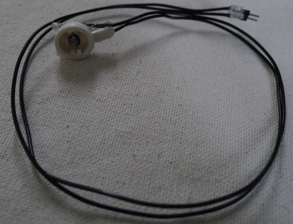
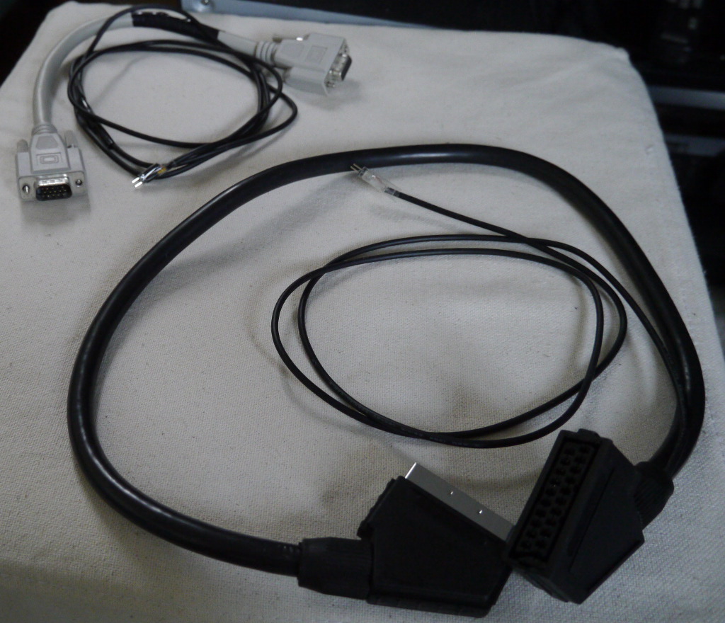
The LDR placed in a plastic case. VGA & SCART extension cables with probe wires.
Parts list
4. Test methodology
A simple black to white transition is used as the test signal. In the analog input signal, this causes the voltages on R, G and B lines to rise from 0.0V to around 0.7V. The voltage of a a single line is fed to the AVR's comparator, where the reference is set to around 0.38V by R4 and R5. When a transition has been detected, a timer is started. It's stopped when the photoresistor senses high enough luminosity. This way, the measurement includes both processing latency and pixel response time. The photoresistor is used as a simple digital input, with a weak pullup (R3) which sets the luminosity threshold. In the next version, this will be replaced by a photodiode/transistor for better accuracy.
Before testing, the monitor should configured to have relatively high contast. ECO modes, adaptive brightness features etc. should be turned off for consistent results. The test uses videos, which include black-white transition between 2 frames. The videos should be viewed full-screen, fully stretched and with looped playback. It is recommended to use a player where the OSD can be disabled to avoid anything extra showing on the screen. The transition should take place at the first scanline, after back porch. This requires that the video playback is synced to vblank (i.e. no tearing). If you are unsure if the playback is vsynced, try this test clip in fullscreen. If there is no tearing, you are ready for testing. Otherwise, try a different player or disabling compositing window manager if you are using one.
Ideally the sensor should detect the transition of the first pixel/dot, but in practice it takes a few scanlines to generate enough luminosity for it. That shouldn't add too much inaccuracy and the test results in my tests were quite consistent (usually sub-1ms variations). The test videos can be downloaded using the followings links:
480p (4:3) version
720p (16:9) version
5. Test instructions
After power is connected to the device, it is possible to test the brightness threshold of the lag tester. The sensor should be initially placed at the top-left corner of the display. The LED shows the status of the input - it should be off when the screen is black, and on when white. If that works, open one of the previous videos in full-screen. Press the button when the screen is black. When the screen turns white, you should get the resulting display latency printed on the character LCD display. The measurement can be restarted by pushing the button again after the playback changes back to black.
If you want to know about the display refresh logic of the display, try placing the sensor in the bottom-right corner of the display and repeat the measurement. Remember to subtract the period of one frame from the result now (e.g. 16ms @ 60Hz), since that is the difference present in input signal between those points. If you get the same result (after subtraction), your display has a constant signal-output latency. If you are testing a plasma display, you should get almost identical value from every point before subtraction. This shows that the upper part of the screen has larger latency than the lower part, as was explained in section 2.
6. HEX and source code
Download
The AVR fuse values can be found in the provided Makefile.
7. Links
Latency mitigation strategies
Latency – the sine qua non of AR and VR
Displaylag.com database
Shmups forum topic on Leo's lag tester
8. Contact info
E-mail: mhiienka(at)niksula.hut.fi