VGA lag tester (original)
NOTE: The version presented here is my original lag tester. It is recommended to use the newer AVR-based tester.
Updated 1.4.2013
Lag tester
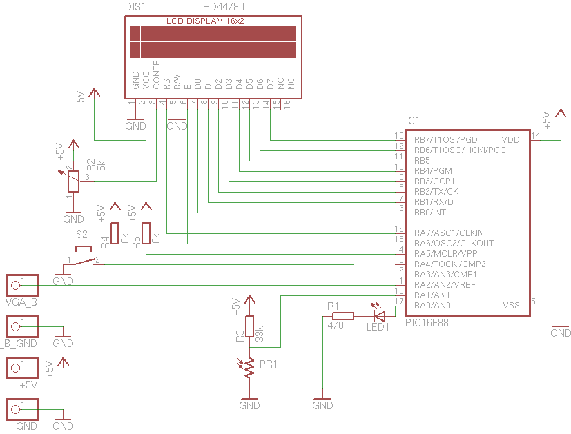
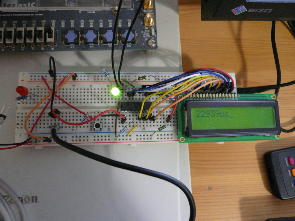
The lag tester (shown below) consists of a microcontroller (PIC16F88), character LCD display, photoresistor, button and LED. The basic working principle is simple: tap one component of the video signal, and calculate the time between a transition in input signal and corresponding pattern in display. This setup requires a PC generating the test signal and VGA breakout cable in addition to the tester device. It'd probably be possible to implement the signal generation with a bit more capable microconroller and tight assembly coding, but generating the signal outside allows more flexibility with resolutions etc. Anyway, the cost of the parts should be below $20.
Parts list
Test methodology
The simplest test signal is a black to white transition. In input (analog) signal, this causes the voltages on R, G and B lines to rise from 0.0V to around 0.7V. The voltage of a a single line is fed to the PIC's A/D converter, and polled continously by the contoller. When a transition has been detected (output is kept at 0.7V until next front porch), a timer in started in PIC. It is stopped when the photoresistor receives high enough luminosity. This way, the measurement includes both signal latency and pixel response time. The photoresistor is used as a simple digital input, with a weak pullup which sets the luminosity threshold.
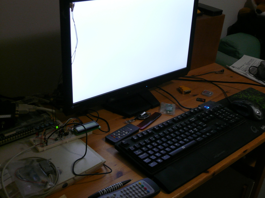
Before testing, the monitor should configured to have relatively high contast. ECO modes, adaptive brigthness features etc. should be turned off for consistent results. The test uses videos, which include black-white transition between 2 frames. The videos should be viewed full-screen (select the video matching the aspect ratio, or stretch it), preferably with a video player where OSD can be disabled (e.g. mplayer). The sensor should be initially placed at the top-left corner of the display. If one wants to know about the display refresh logic of the display, the sensor can be subsequently placed in other locations. The transition should take place at the first scanline, after back porch. This requires that the video playback is synced to vblank (i.e. no tearing). If you are unsure if the playback is vsynced, try this test clip in fullscreen. If there is no tearing, you are ready for testing. Otherwise, try a different player or disabling compositing window manager if you are using one.
Ideally the sensor should detect the transition of the first pixel/dot, but in practice it takes a few scanlines to generate enough luminosity for it. In practise, that shouldn't add too much inaccuracy and the test results should be quite consistent (~0.3ms variations in my tests). The test videos can be downloaded on the followings links:
480p (4:3) version
720p (16:9) version
HEX and src for PIC
HEX for PIC16F88
Source code
The code is written to be compiled with SDCC compiler (defines, include files etc.). I've stumbled into some bugs with SDCC for PIC, so I can't generally recommend it for PIC-projects. For example, it has problems with 32bit variables, so the resulting latency is handled as 16bit, where the highest value is 65535 (us). I didn't want to use prescalers and drop to ms range, so except overflows if you have a pathetic display with over 65ms latency. This is one of the reasons the next version will be done for AVR.